
HSMtec 3D printed circuit board: the self-supporting 3D design
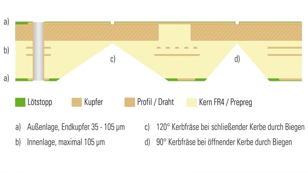
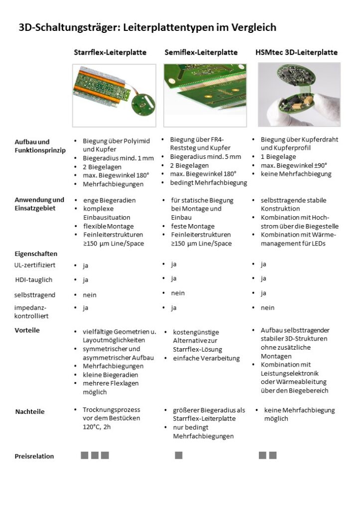
The HSMtec 3D printed circuit board does not require flex foil at the bending point. With this technology, copper wires and copper profiles pressed into the FR4 material of the multilayer are used as bendable material. The FR4 is removed at the bending edges with notches. At these predetermined bending points, individual segments can be aligned with an angle of inclination of up to ±90°. The special feature: The copper profiles allow a self-supporting construction, whereby high currents or heat are also conducted over the bending edge. In this way, multidimensional applications with power electronics can be combined across the bending area or with rapid heat spreading in circuit carriers for LEDs.
The design is predestined for one-off bends, e.g. for applications where the flexible area is only bent for the installation of the assembly. The PCB is qualified in accordance with DIN EN 60068-2-14 and JEDEC A 101-A and audited for aviation and automotive applications. A further advantage: the low moisture absorption eliminates the need for thermal pre-treatment during soldering. In addition, all other processes are fully compatible with the standard process.
The possibilities of this 3D design are demonstrated by eCube - a cube created in a research project led by Continental Automotive. The aim was to develop a three-dimensional cube- or cuboid-shaped PCB based on an existing Continental standard PCB layout for an engine control unit. The components were to be mounted on the PCB on an assembly line using the existing placement machines. After assembly, the PCB was folded at the defined bending edges and the resulting butt edges were electrically and mechanically connected.
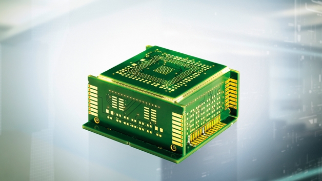
After connecting the edges, the cube was aligned on the base plate and joined together both electrically and mechanically. The cube is connected to the motherboard of the motor controller via a ball grid array structure. What initially appears to be a complex process, namely mounting a multi-dimensional PCB construction on the actual PCB of the motor controller, is a technically clever and economical solution on closer inspection. The multidimensional PCB is used to design a module that can be manufactured in different variants, but in a standardized way, while making use of the available installation space.
Expert tip: The perfect balancing act
Multi-dimensional PCBs bring added value to the electronic assembly. Although the 3D PCB is more valuable and more expensive to manufacture than a rigid PCB, the system costs of the overall solution are reduced. The three-dimensional PCB is laid out and manufactured as a two-dimensional PCB and then brought into the desired three-dimensional shape after assembly. From the PCB manufacturer's point of view, the focus is on manufacturability and it is important to strike a balance between stability, flexibility and accuracy. Stability, so that the finished PCB can be assembled and is suitable for reflow ovens and testing; flexibility, so that the PCB can be easily and quickly separated from the panel; and accuracy, because too many retaining strips would leave unclean traces.
3D printed circuit boards: three technologies, three examples - Part 1
3D printed circuit boards: three technologies, three examples - Part 2